Michael Song's Projects
Animation of Earth-to-Mars Spacecraft Trajectory
Project duration
June-July, 2021
Introduction
NASA’s successful landing of Perseverance Rover on Mars earlier this year inspired me to uncover the math and logic behind it. Our AP physics class covered the topics of Kepler’s laws of planetary motion, but only briefly explained how they are applied to inter-planet spacecraft. In this project, I explored the physics behind the long journey of the Earth-to-Mars spacecraft by making an animation of motions of the Earth and Mars, together with the trajectory of the spacecraft launching from Earth and finally meeting Mars.
Click here to jump to see the animation result.
Objectives
The objectives of this projects include
- simulating the trajectory of the spacecraft that takes the Hohmann Transfer orbit.
- simulating the motion of both Earth and Mar at the same time as the spacecraft.
- computing the instantaneous lapsed-time, speed of the spacecraft, the distance from the spacecraft to Earth, Mars and Sun, respectively.
Methods
1. Physics
Due to the presence of gravity and that both Earth and Mars are moving, the spacecraft is not aimed at where Mars was at launch time. Instead, it aims at a point ahead of the current location of Mars, so that when the spacecraft arrives that point, Mars also arrives at exactly the same time.
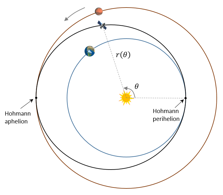
With different launch speed, the spacecraft can fly along a variety of elliptical paths and meet the orbit of Mars at different location. Among these single-elliptical orbits, the Hohmann transfer orbit is the most efficient one that requires the least launch fuel. Hohmann Transfer Orbit refers to the elliptical orbit that touches the Earth orbit at Hohmann perihelion at launch time and touches the Mars orbit at Hohmann aphelion at arrival time, as shown in Figure 1.

Figure 1 Illustration of the orbits of Earth, Mars and the Earth-to-Mars spacecraft.
For the tasks in this project, the most important physics are Kepler’s laws of planetary motion
-
Kepler’s first law: The orbit of a planet is an ellipse with the Sun at one of the two foci. According to this law, the orbits of the Earth, Mars and spacecraft are all ellipses. However, the orbit of Earth and Mars are just slightly elliptical, therefore, they are approximated to be circular and within the same plane in order to simplify the task.
-
Kepler’s second law: A line segment joining a planet and the Sun sweeps out equal areas during equal intervals of time. Because the time duration of each frame in our animation is the same, the second law means that, during every animation frame, the area swept by the line segment joining the spacecraft and the Sun is the same. This relationship provides a relatively easy way to determine where the spacecraft should be located at each frame of the animation.
-
Kepler’s third law: The square of a planet’s orbital period is proportional to the cube of the length of the semi-major axis of its orbit. This law provides the relationship of orbit radius and period among the three “planets” (Earth, Mars and the spacecraft). This is critical because we need this information to calculate: when to launch and what’s the correct relative location between Mars and Earth so that the spacecraft and Mars will arrive at the same location when the spacecraft reaches Mars’ orbit.
Another important concept that needs to be mentioned is **the orbital-energy-invariance law**, also known as the vis-viva equation [Wikipedia], that gives the relationship between the speed of the orbiting body, \(v\), and its distance to the Sun, \(r\).
where \(a\) is the length of the semi-major axis of the elliptical orbit, \(G\) is the universal gravitational constant, and \(M\) is the mass of the sun. For our solar system, \(GM = 1.32712440018 \times {10^{20} }{\rm{\;} }{m^3} \times {s^{ - 2} }\). This equation will be used to calculate the speed of the spacecraft, given \(r\), during the flight.
2. Mathematics
Based on Kepler's first law, the Hohmann Transfer orbit can be expressed as an elliptical equation. I found that the polar coordinate system is more convenient than the equivalent Cartesian coordinate system to compute positions for each frame of animation, as shown below.
where \(r\) is the distance from a point on the ellipse (spacecraft) to the origin (Sun), \(\theta \) is the polar angle of the ray (from the origin to this point), defined to have 0° at the 3 o’clock direction (Hohmann perihelion), and to increase for rotations in counterclockwise orientation; \(A = 1.261845{\rm{\;} }AU\) (Astronomical Unit) is the length of the Hohmann semi-major axis, \(e = 0.207511\) is the eccentricity of the Hohmann orbit.
2.1 Derivation of spacecraft’s trajectory per animation frame
It’s quite easy to plot ellipses, but it’s challenging to animate the spacecraft motion because its motion is non-uniform along the elliptical orbit. When the spacecraft flies along the elliptical orbit from its perihelion to its aphelion, its distance to the Sun is keep increasing. The vis-viva law tells us that its linear speed and angular speed are decreasing. This means that we cannot simply move the spacecraft by the same amount of angular increment or linear increment for each equal-duration time frame of the animation. Instead, we have to figure out where the spacecraft is at each specific time frame.
This is achieved by using Kepler's second law: the areas swept by the Sun-spacecraft ray during the \(i\)-th equally-spaced time frame of animation are the same. If the animation contains \(N\) frames to cover the spacecraft’s entire flight, then
where \(A\) and \(B\) are the Hohmann semi-major and semi-minor axes, respectively.

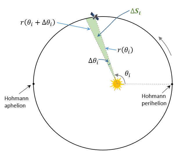
Figure 2 Illustration of calculation of \({\Delta S_i}\).
A representative \({\Delta S_i}\) is illustrated in Figure 2 and its area can be computed as a triangle:
Combining Equations (3) and (4), substituting \(r\left( { {\theta _i} } \right)\) and with Equation (2), using trigonometry, approximating and based on Taylor series expansion, we can solve the equations for as a function of \({\theta _i}\) as following:
Then the new angular position for the next time frame \({\theta _{i + 1} }\) can be computed as
The \(x\)- and \(y\)-coordinates can be easily calculated as
\({v_{x,0}} = {v_0}\cos \theta \)
\({v_{y,0}} = {v_0}\sin \theta \)
(7)Equations (5) through (7) allows us to animate the elliptical trajectory from the beginning, then find the coordinates of the next frame, one followed by another one, until the spacecraft meet the Mars.
2.2 Derivation of circular trajectories of Earth and Mars
For Earth and Mars, the derivation is much simpler because they are approximated to uniform circular motions. The only thing we need to do is to find out the location of Mars at the moment when the spacecraft is launching from the Earth at the Hohmann perihelion so that the spacecraft can meet the Mars at the Hohmann Aphelion. This can be determined based on Kepler’s third law:
where \(T\) denote the orbiting period, and \(R\) is the radius or semi-major axis of the orbits. The subscripts \(E\), \(M\) and \(S\) denote Earth, Mars and the spacecraft, respectively.
Some simple derivations give us
\({\phi _{S,Start} } = 0\) \({\phi _{S,End} } = 180^\circ \)
\({\phi _{E,Start} } = 0\) \({\phi _{E,End} } = 180^\circ \times \sqrt {\frac{ { {R_S}^3} }{ { {R_E}^3} } } \approx 255^\circ \)
\({\phi _{M,Start} } = 180^\circ \times \left( {1 - \sqrt {\frac{ { {R_S}^3} }{ { {R_M}^3} } } } \right) \approx 44^\circ \) \({\phi _{M,End} } = 180^\circ \)
(9)2.3 Calculation of the flight stats of the spacecraft
For the \(i\)-th animation frame, the instantaneous speed of the spacecraft \({v_{S,i} }\) can be calculated from its distance to the Sun using the vis-viva equation as follows:
The “real-time” travel distance of the spacecraft \({L_S}\) is approximated as an integration of the arc length over individual frames. The perimeter of an ellipse (distance traveled) is significantly harder to calculate and use approximations instead of an exact formula.
The “real-time” distances from the spacecraft to Earth, Mars and Sun can be simply calculated based on their current locations.
3. Computer programming
The animation part of this project was implemented using Python with Matplotlib package. The major functions include
-
The
generate_animation_points()function precomputes the x- and y-coordinates of Earth, Mars and the spacecraft for all animation frames using the equations derived above -
The
init()function is defined to clear the data buffer and text contents. It must return all drawing and text objects that need to be refreshed during animation. -
The
animate(i)function is the core part of animation to refresh the drawing and text objects. -
The
main()function callsanimation.FuncAnimation()from the Matplotlib package to make animation, which repeatedly calls theanimate(i)function above to refresh the display. It also saves the animation to video files.
Results and Discussions
The animation video is shown below. Please click the Replay button to view the video.
Summary
In this independent project, I was inspired by the successful landing of Perseverance Rover on Mars to make an animation of the trajectories of Earth, Mars and the spacecraft launched from Earth to Mars via the Hohmann Transfer Orbit. This project involves interesting knowledge in physics behind the story, math for solving the problem, and programming to implement the solution. In the end, the objects “really fly in the animation” as designed and expected. Cheers!
Our salute goes to those pioneers, scientists, engineering, workers and all people who worked hard to make those accomplishments happen, including the Perseverance Rover and a lot more.